F5 Firewall Solutions > Advanced Multi-Layer Firewall Protection > Module 1: F5 Multi-layer Firewall Source | Edit on
Lab 2: Leverage LTM Policies To Direct SSL Terminated Applications To Secondary Virtual Servers
What is SNI? Introduced in TLS 1.0 as a TLS extension, Server Name Indication (SNI) allows the client to send the hostname they are trying to connect to in the SSL handshake. This allows the Application Delivery Controllers (ADC) such as the BIG-IP and the Application servers to identify the appropriate application the client is trying to connect to. From this information, the ADC can respond with the proper SSL certificate to the client allowing the ADC to provide SSL enabled services for multiple applications from a single IP address.
LTM policies are another way to programatically modify traffic as it is flowing through the data plane of the BIG-IP. This functionality can also be accomplished with F5 iRules. The advantage this has over iRules is that LTM policies can be modified and appended to the existing configuration without replacing the entire application configuration. This lends itself to being updated through the CLI or via the REST API easily.
If you make a single change to an iRule, the entire iRule needs to be re-uploaded and applied.
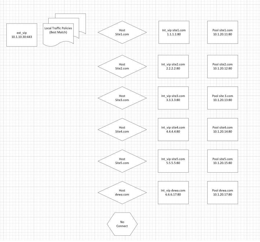
The LTM policy is what directs application traffic to flow from the external virtual server to the internal virtual servers based on the Layer 7 request. In this case, since we are using SNI to terminate multiple applications (mysite,yoursite,theirsite, api, downloads) we need to be able to direct that traffic to the appropriate application pools. Some can even come back to the same application pool.
Whether it is based on the hostname or the URI path, the request can be forwarded to a different virtual server or an application pool of servers.
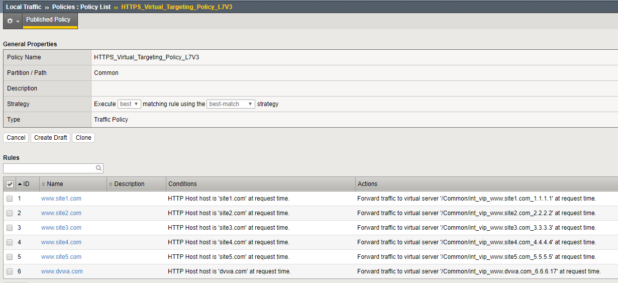
Inspect the LTM Policies
Take a few minutes to open the draft policy and review the iptions. Policy is a very flexible tool to direct traffic based on the packet content. In this use case we distribute traffic to a subset of internal VIP’s, Policy can be configured to forward traffic directly to pools or nodes based on the packet content and many other attributes
Note
As shown in this diagram, there is an external VIP and internal VIPs. The external VIP has the local traffic policies on it.
Navigation: Local Traffic > Policies : Policy List
Navigation: Select HTTPS_Virtual_Targeting_Policy_L7V3 from the published policies
Verify that the Policy is assigned To The External Virtual Server
Navigation: Local Traffic > Virtual Servers : Virtual Server List
Navigation: Click the EXT_VIP_10_1_10_30
Navigation: Click the Resources Tab
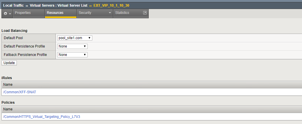
Note
there is a policy and an iRule is assigned to the VIP:
Create An ACL to allow web traffic and SSH
The rules created in this section allow basic connectivity to the resources. We will add enforcement rules at the Virtual server level to demostrate functionality
On bigip01.f5demo.com (10.1.1.4) create a rule list to allow traffic. A logical container will be created before the individual rules can be added. You will create a list with rules to allow port 80 (HTTP), 443 (HTTPS), and 22 (SSH) to servers 10.1.20.11 through 10.1.20.17 We will also create a rules which allows HTTPS and SSH traffic to access 10.1.10.30
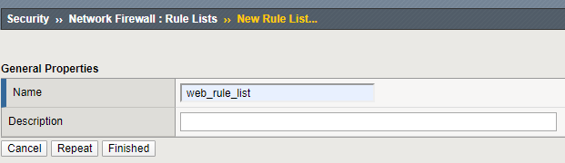
Create a container for the rules by going to:
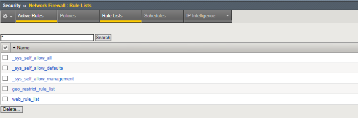
Navigation: Security > Network Firewall > Rule Lists
Navigation: select Create
For the Name enter web_rule_list, provide an optional description
Navigation click Finished
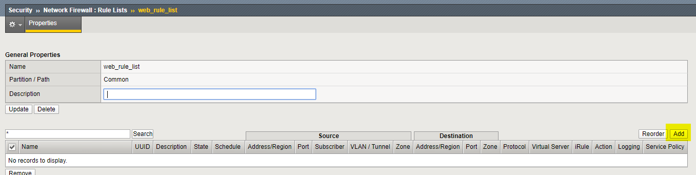
Navigation Select the web_rule_list by clicking on it in the Rule Lists table
Navigation click the Add button in the Rules section.
Add a rules into the list to allow HTTP, HTTPS, and SSH traffic as described in the next steps
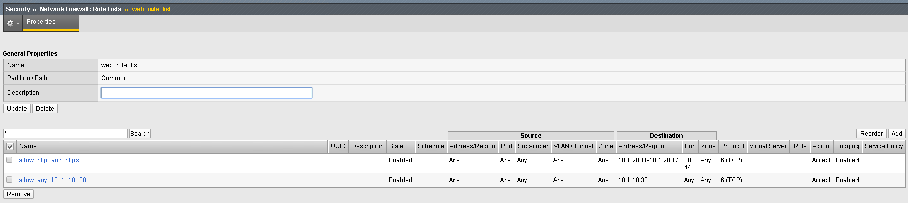
| Name | allow_http_and_https |
|---|---|
| Protocol | TCP |
| Source | Leave at Default of Any |
| Destination Address | Pulldown Specify Address Range 10.1.20.11 to 10.1.20.17, then click Add |
| Destination Port | Pulldown Specify… Port 80, click Add Specify… Port 443, click Add |
| Action | Accept |
| Logging | Enabled |
Navigation: Click Repeat
Add a rule into the list to allow HTTPS to Virtual Server 10_1_10_30.
| Name | allow_any_10_1_10_30 |
|---|---|
| Protocol | TCP |
| Source | Leave at Default of Any |
| Destination Address | Pulldown Specify…10.1.10.30 then click Add |
| Destination Port | Pulldown Specify… Port Any, then click Add |
| Action | Accept |
| Logging | Enabled |
Navigation: Click Finished
Navigation: Click Finished
Assign the Rule List to a Policy
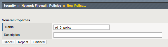
Navigation: Security > Network Firewall > Policies
Navigation Click Create
For the Name enter rd_0_policy, provide an optional description
Navigation click Finished.
(Note: We commonly use “RD” in our rules to help reference the “Route Domain”, default is 0)**
Navigation Edit the rd_0_policy by clicking on it in the Policy Lists table,
Navigation click the Add Rule List button.
Navigation For the Name, start typing web_rule_list, you will notice the name will auto complete,
Navigation select the rule list /Common/web_rule_list, provide an optional description
Navigation click Done Editing.
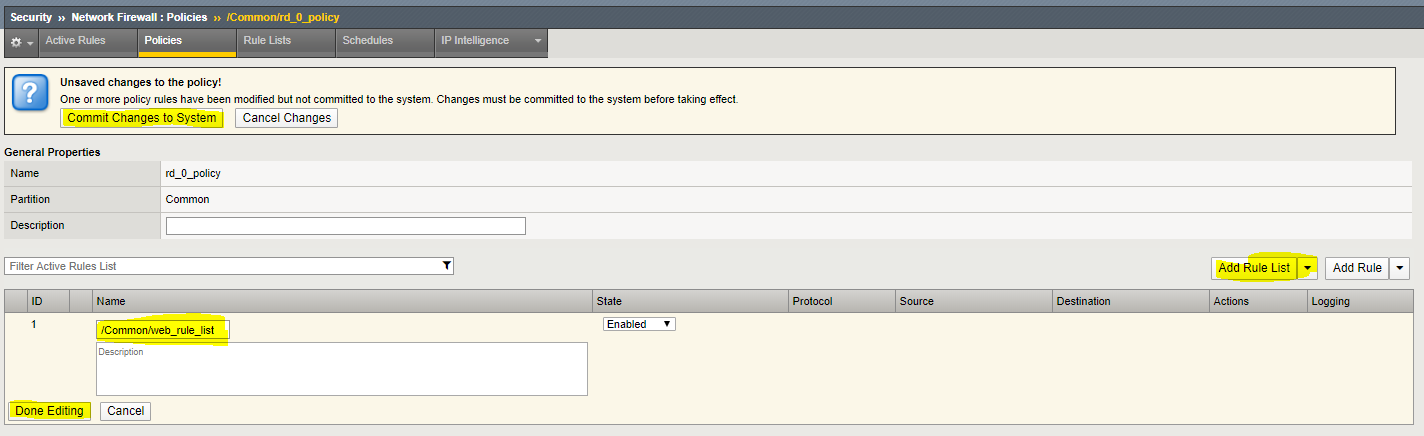
You will notice the changes are unsaved and need to be committed to the system. This is a nice feature to have enabled to verify you want to commit the changes you’ve just made without a change automatically being implemented.
Navigation click “Commit Changes to System”
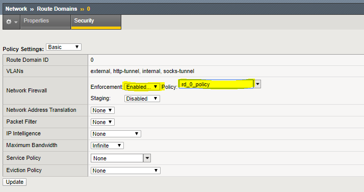
Assign the rd_0_policy to Route Domain 0
Navigation: Network > Route Domains
Navigation: Click on the “0” to select Route Domain 0
Navigation: Select the Security Tab
Set Enforcement to Enable and select the rd_0_policy
Navigation Click Update
Configure BIG-IP Firewall in ADC Mode
By default, the Network Firewall is configured in ADC mode, a default allow configuration, in which all traffic is allowed through the firewall, and any traffic you want to block must be explicitly specified.
The system is configured in this mode by default so all traffic on your system continues to pass after you provision the Advanced Firewall Manager. You should create appropriate firewall rules to allow necessary traffic to pass before you switch the Advanced Firewall Manager to Firewall mode. In Firewall mode, a default deny configuration, all traffic is blocked through the firewall, and any traffic you want to allow through the firewall must be explicitly specified.
In deployments where there are a large number of VIP’s, deploying in Firewall mode would require significant preperation. Firewall functionality is easier to introduce in ADC mode.
Navigation: Security > Options > Network Firewall
| Virtual Server & Self IP Contexts | Accept |
Navigation Click Update
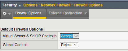
Open the Firewall Options tab
Validate Lab 2 Configuration
Note
Open a tab on the Chrome Browser to test access to the URL’s below
Validation: This lab is using self-signed certificates. You can either open a web browser on the test client or run CURL from the CLI to validate your configuration.
You will need to accept the certificate to proceed to the application sites
URL: https://site1.com

URL: https://site2.com

URL: https://site3.com

URL: https://site4.com

URL: https://site5.com

URL: https://dvwa.com    Username:  admin    Password: password
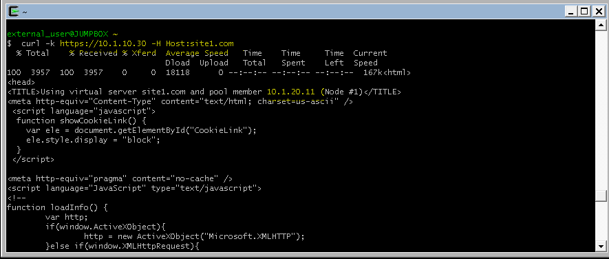
With curl you need to use the -k option to ignore certificate validation
Note
From a terminal window (use Cygwin on Win7 Client Desktop). Curl will let us do some of the additional testing in later sections. If you scroll up to the text immediately following the command you will see the IP address of the pool member you connected to.
curl -k https://10.1.10.30 -H Host:site1.com

curl -k https://10.1.10.30 -H Host:site2.com

curl -k https://10.1.10.30 -H Host:site3.com

curl -k https://10.1.10.30 -H Host:site4.com

curl -k https://10.1.10.30 -H Host:site5.com
Note
for site 1 connected to 10.1.20.11, site 2 10.1.20.12 etc:
Note
This completes Module 1 - Lab 2: